Here are the steps in drawing an isometric cube. Note: the third figure is a canonical "isometric cube"; the fourth image has been shaded to increase and/or aid in visual comprehension. Or as we say, to "reduce isometric ambiguity".
Isometric drawing, like perspective drawing, represents three-dimensional forms on a
two-dimensional plane.
Here's an isometric cube (or an "isometric drawing of a cube"):
Here are the steps in drawing an isometric cube. Note: the third figure is a canonical "isometric
cube"; the fourth image has been shaded to increase and/or aid in visual comprehension. Or as we
say, to "reduce isometric ambiguity".
Note that every angle is either 120, 60, or 30 degrees, and every line segment is equal in length. In more complicated drawings - for example of a part that needs to be machined - if you put a ruler up to any line segment of an isometric drawing, you can figure out just how long the corresponding (real-world) edge needs to be. This can be very valuable in communication between someone specifying a part, and someone else manufacturing that part.
The isometric grid is a framework that is used to design isometric forms. The grid is based on the same proportions as an isometric cube, composed of vertical lines and 30� diagonals that intersect at equal intervals. The word 'isometric' is derived from the ancient Greek for 'equal measure'.
Note that in the above grid, a cube is already drawn; note also that it's been shaded for ease
of interpretation. Not all systems - for example blueprint drawings - support such
shading.
Isometric and perspective drawings have some distinct differences:
In the perspective drawing it is hard to tell whether you are looking at cubes or cuboids as the receding shapes are foreshortened.
In the isometric drawing, the cubes are more obviously cubes, because all edges are represented by line segments of equal length.
One thing you will notice in these and other isometric sketches is their spatial ambiguity. Without shading or other special effects designed to ameliorate this ambiguity, planes flip back and forward in view, advancing and receding, as they have none of the foreshortening that you find in perspective drawing. Both the nearest and furthest forms are the same size, thereby confusing your visual interpretation of the image. This is a quality of isometric drawing that artists and designers often exploit. The Penrose Triangle - which makes the impossible possible - is an example.
To resolve the ambiguity inherent in many isometric drawings - graphic artists can use techniques such as you see here, and others, including shading, coloring, even applying wood-grain or other visual cues to the various surfaces. Since pure isometric drawings - consisting of nothing but black lines on white paper - lack any of these features, their use is limited to drawing systems that support these enhancements. Though these techniques can work, they can also fail; for example when making a black-and-white scan or photocopy of an isometric drawing which has been shaded.
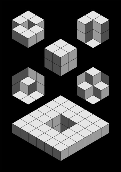
Here for example are six isometric drawings, five of which are ambiguous:
All the drawings except the cube are ambiguous.
Consider for example the drawing on the upper left. You may think that you see and understand it, clearly and for certain. With the right tools and materials you could make it. But another viewer/interpreter can easily see it a second way, that is materially different. Given only the isometric drawing - with no other documentation, drawing, communication, nor shared understanding - there is no way to resolve this ambiguity, which can result in useless parts being manufactured, wasted money, delays, and failed projects. Not to mention arguments that can never be authoritatively settled and degenerate into table-pounding, recriminations, and failed business relationships.
|
�
|
(swipe left and right to view shading) |
The drawing in the upper left is a special example of how one can resolve the ambiguity of a "pure" (black-lines-on-grid only) isometric drawing, using shading techiques. However the other figures show that even this does not work in all cases. In fact these figures - other than the cube - are well-known examples of optical illusions.
Even with shading:
Artists can use the isometric grid to explore - and exploit - the creative possibilities of isometric ambiguity. This is a process of trial and error, searching for and coming up with combinations of cubes and other figures that look visually interesting.
Non-artists, however, need to keep in mind that despite the advantages of isometric drawing, the well-known problem of "isometric ambiguity" can never be resolved, without augmentation of some sort. Shading the drawings is a half-step which as you have seen doesn't even work in all cases; plus it creates its own problems (such as incompatibilities between different storage and representation systems) not inherent in pure/canonical isometric drawings.
To safely and adequately (definitively) represent 3-dimensional objects in/on a 2-dimensional drawing therefore requires using multiple graphical techniques. Architects rely on plans, elevations, artist's sketches/representations, perspective drawings, and in many cases (such as oil refineries), actual 3-dimensional models. Engineers use their own sets of tools and conventions; different but (hopefully) accomplishing the same goal. And of course nowadays computerized solid-modeling allows effective storage, representation, and communication.